

Introduction
Transport Scotland has proposed major investments in railway electrification, with the replacement of diesel multiple units being a priority. Considerable interest is being shown in the potential of hydrogen fuel-cell and battery-electric trains for secondary routes where the business case for electrification is not strong.
The West Highland lines linking central Scotland to Oban, Fort William and Mallaig are a prime example, involving relatively long journeys, with few intermediate stations, prolonged gradients and many speed restrictions.
Early in 2020 Transport Scotland and Scottish Enterprise announced support for the development of a hydrogen fuel-cell/battery-electric multiple unit for trials in Scotland, with the Hydrogen Accelerator group at St Andrews University involved in management of the project. A contract for converting a former ScotRail Class 314 three-coach electric multiple unit (see Figure 1) to a hybrid configuration was awarded in December 2020 to a group of companies led by Arcola Energy.
This project is also intended to help promote new industry/academic collaborations, with the work on rail powertrain simulation between Arcola and a group at Glasgow University being an early example.
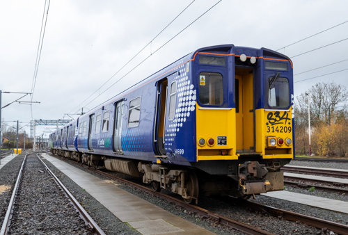 Figure 1: The former ScotRail 314 unit to be converted to hydrogen fuel-cell hybrid
The powertrain
Hydrogen fuel-cell stacks are characterized by a sluggish response to demanded power-level changes and their efficiency depends on the operating condition. Powertrain control strategies may therefore involve fuel-cell stack operation with The battery pack recharges through regenerative braking or from available power from the fuel-cell stack.
Figure 2 shows typical powertrain components and interconnections. The stack has a unidirectional link but connections to the inverter and batteries are bi-directional.
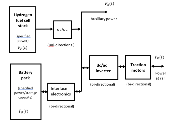
Figure 2. Powertrain block diagram
Computer simulation models
Mathematical models for longitudinal train motion are well established1-3 and most involve second-order nonlinear ordinary differential equations, derived using Newton’s second law:
Mass × Acceleration = Tractive force at the rail – Sum of all resistive forces (1)
Acceleration can be found directly from (1) and train speed and distance travelled can then be determined by integration.
It is also possible to work backwards from a given speed or distance schedule to the tractive force using “inverse simulation”. Analysis of road-vehicle powertrains is often approached this way using static or quasi-static models4. In the simplest (“direct”) method (1) is rearranged as follows:
Tractive force at the rail = Mass × Acceleration + Sum of all resistive forces (2)
The tractive force T(t) is then multiplied by the velocity to give the required power at the rail PR(t), and this allows consideration of options for fuel-cell power and battery power (see Figure 3).
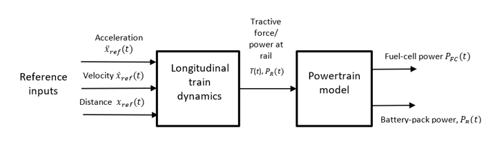 Figure 3: Direct inverse simulation block diagram
Another approach1 involves high-gain feedback in which the reference input is compared with the corresponding model variable to determine the tractive force T(t) and power at the rail PR(t). Powertrain analysis is then possible, as in the direct approach.
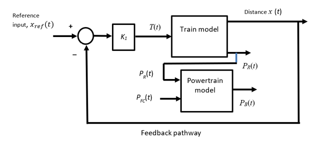 Figure 4: Block diagram – feedback approach
Modelling and simulation of powertrain components
In the Glasgow University investigations, the fuel-cell stack and battery-pack have been represented by ideal sources with specified power and battery energy-storage levels. A battery efficiency factor accounts for energy losses between charge and discharge and efficiency factors are included for power electronic sub-systems and motors. The tractive force is subject to an adhesion limit, and this is applied during braking as well as during acceleration.
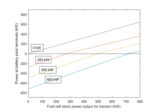
Initial estimates of component sizes can be found from steady-state analysis. For example, for a given fuel-cell power level, an increase in power demanded at the rail is met by increased power from the battery pack (see Figure 5). The battery pack also switches from discharge to charge mode when power at the rail falls below critical levels. The storage capacity needed to meet transient demands can be established through dynamic analysis.
Route modelling, driver actions and reference data
Route modelling is based on gradient profiles or elevation information, together with speed limits. Global positioning system (GPS) information can give speed and elevation from on-train measurements, thus providing both a speed reference and gradient information. However, care is required in the application of appropriate GPS data corrections, especially for elevation. Published gradient information, available for most routes, provides a good alternative. Reference schedules may also be based on quasi-steady straight-line segments for speed or distance or derived using forward simulation.
Inverse simulation results
a) Direct approach
Arcola engineers have used a direct inverse simulation approach for a model of the hybrid Class 314 on two routes. One is the Bo’ness and Kinneil heritage line where some sections involve gradients as steep as 1 in 58, with an overall speed limit of 20 mph and some more severe local restrictions. The speed schedule used involves straight line segments representing phases of constant acceleration and phases involving constant speed. Such quasi-static approximations can provide good estimates of power and energy requirements. Reference time histories obtained from a forward simulation model of an existing diesel multiple unit have potential advantages by allowing for train dynamics and thus avoiding physically implausible transients that can arise in the quasi-static approach.
b) Using the feedback approach
The University group has applied the feedback approach to a Class 314 train model on the Bo’ness and Kinneil route using speed profiles and elevation data provided by Arcola Energy. Gradient information was derived from the elevation data. Results matched those found using the direct method very closely.
Further work is under way at Glasgow using the feedback approach for the Kilmarnock to Dumfries route to obtain results to compare with those found by Arcola engineers using their direct approach. The train model within the feedback loop represents the hybrid Class 314 with a reference input from a three-coach Class 159/1 diesel multiple unit simulation3. Gradient profiles and speed restriction data are from publicly available sources.
The current work differs from the approach used previously for the West Highland lines2,3 where special route sections were defined to provide typical (but simplified) profiles. One such section was approximately 15 km long with a line speed limit of 96 km/hr, involving five phases as follows: a) an initial length of 4 km on level track, b) a section with a gradient of 1 in 60, c) a further section of level track continuing to the destination, d) a coasting phase starting at 11.3 km and e) a final braking phase starting at 14.3 km to bring the train to rest. The reference input was generated from the forward simulation model for the Class 159/1 three-coach unit3 That reference model was based on (1), involving a simplified representation of the diesel engines and transmission4.
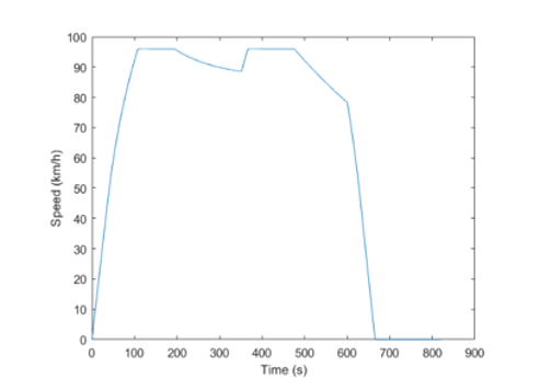
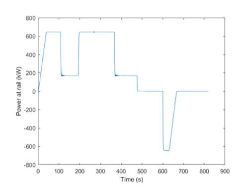
Figure 6 shows the speed versus time plot from the Class 159/1 simulation. This record gave a journey time of just over 11 minutes and this, or the corresponding distance time history, provided the reference used for inverse simulations of the hybrid unit3. Figure 7 shows the time history of power at the rail found using the feedback method to meet this schedule with the hybrid unit. This is influenced, very strongly, by the nature of the route and is subject to a tractive force adhesion limit of 50 kN. During acceleration from rest, the transition from the adhesion-limited condition to the constant power condition occurs at a speed of 12 m/s and the tractive force then falls inversely with the speed. During regenerative braking the speed drops until it reaches the 12 m/s threshold when frictional braking is applied, with a negative force at the rail equal to the adhesion limit.
Powertrain component sizing
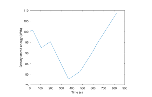
Inverse simulation results (see Figure 7) show a maximum power at the rail (PR(t)) of about 650 kW and this establishes ratings for the traction motors. Figure 5 suggests that, with a fuel-cell stack supplying 500 kW, the battery pack power output must be about 220 kW. Although such steady-state analysis provides a first estimate of powertrain component ratings, dynamic investigations can provide more insight about stored-energy requirements of the battery. Figure 8 provides relevant simulation results showing a maximum rate of change of stored energy for the test route of - 6.1 kWh/min and an average recharging rate of 4.9 kWh/min during coasting, braking and stationary periods. The battery is fully recharged about one minute after the train comes to a halt. Findings like this from the test route have been used to estimate powertrain ratings for the Fort William line3.
Increasing the fuel-cell stack power rating to 600 kW reduces the battery discharge to -4.5 kWh/min while the re-charge rate is increased to about 6 kWh/min, thus allowing possible use of a smaller battery pack.
The inverse approach allows sensitivity analysis for other model parameters since each simulation run uses the same reference schedule. For example, simulation shows that reduction of the train mass by 15 tons reduces the maximum power drawn from the battery by about 25 kW. Effects of journey time changes can also be found through time-scaling of the reference input, and this is described in reports of the earlier work1-3.
Discussions and conclusions
Hydrogen fuel-cell electric powertrains provide a route to decarbonizing rail on lines where electrification is difficult to achieve.
Optimal powertrain component sizes depend on route characteristics, with relatively flat routes and operation at constant speed favoring large fuel-cells, while routes with prolonged and steep gradients or larger accelerations require larger batteries. Specifications for lengthy routes involving steep and prolonged gradients such as those encountered in the Scottish Highlands present significant difficulties.
This sensitivity to route characteristics highlights the benefit of using inverse modelling techniques as a straightforward way to define powertrain characteristics. Research on modelling and simulation techniques provides opportunities for further collaboration between academic research groups and industrial design and development teams.
References:
1. Murray-Smith DJ. Development of an inverse simulation method for the analysis of train performance, Proc IMechE Part F: J Rail and Rapid Transit 2018; 232(5): 1295–1308. http://eprints.gla.ac.uk/148116/1/148116.pdf
2. Murray-Smith DJ Modelling and simulation of hybrid electric trains powered by hydrogen fuel cells and batteries for routes in the highlands of Scotland: Preliminary results. Report for Scottish Association for Public Transport, June 2020. http://eprints.gla.ac.uk/219364/1/219364.pdf
3. Murray-Smith DJ Modelling and simulation of hybrid electric trains powered by hydrogen fuel cells and batteries for routes in the highlands of Scotland: Results for the case of a three-coach multiple unit train. Report for Scottish Association for Public Transport, August 2020. http://eprints.gla.ac.uk/222731/1/222731.pdf.
4. Millo F, Rolando I and Andreata, M Numerical simulation for vehicle powertrain development. In J. Awrejcewicz (ed), “Numerical Analysis – Theory and Application”, IntechOpen, London, 519-540.